The sEMG (Surface Electromyography) Robotic Limb was my final year design project for my engineering undergrad degree. My teammates and I spent 8 months working on the project, custom building some parts ourselves, and programming other commercially available systems to assemble it all together into the sEMG Robotic Limb. Our premise was to better enable control of a robotic arm's movements by replacing common, bulkier systems (such as joysticks or mechanically mimicking systems) with a more intuitive and slimmer design.
The sEMG Robotic Limb is designed around three main systems:
• EMG signal circuit - custom designed and built
• FPGA* signals processing and "operating system" - Xilinx ML505 Virtex 5 FPGA board
• Robot arm - Crustcrawler AX12
In summary, the EMG circuit detected and modified the signals coming from an operator's muscles, which were then sent to the FPGA to be dechiphered into commands for the robot arm's movements. Details of how each part functioned are included below along with photos and videos of our project.
*Field Programmable Gate Array

EMG Circuit
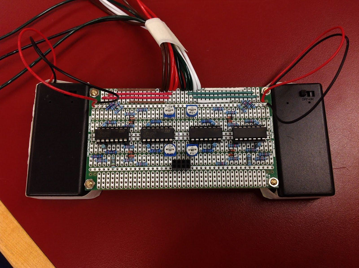
This PCB contains four EMG circuits, allowing for four different muscle groups to be detected simultaneously.
A video showing the EMG circuit and its output signal into an oscilloscope. Here, we are measuring only the magnitude of the signal in volts.
FPGA
The second stage of the project involved reading the EMG signals, and making sense of what they mean. This stage contains the ADC, an initializer, a state machine, and a serializer. Our system uses these components to automatically set 'thresholds" for different levels of muscle contraction (from relaxed to flexed) determined from an operator's test set of signal values, matching the levels to their corresponding arm states in the state machine.
The second stage of the project involved reading the EMG signals, and making sense of what they mean. This stage contains the ADC, an initializer, a state machine, and a serializer. Our system uses these components to automatically set 'thresholds" for different levels of muscle contraction (from relaxed to flexed) determined from an operator's test set of signal values, matching the levels to their corresponding arm states in the state machine.
Early systems integration test. Only half of the robotic arm was tested, located in the bottom right of the video.
Robotic Arm
The robotic arm represents the final stage of the project. As it was a commercially available product, the main work involved integrating the commands between the servos and FPGA through a RS232 serial connection.
The prototype sEMG Robotic Limb at the completion of our project. This video shows single arm manipulation of the robotic arm, capable of detecting grip, bicep contraction, and shoulder rotation. However, complications arose after extended periods of use, and the resulting jittery motion can be seen in the video.
sEMG Robotic Limb - some thoughts
By the end of our project, our scope had shrank significantly (reducing our movement states to only two levels), and we encountered issues which impacted usability that we could not solve in time:
EMG signals
For this project, we utilised only one aspect of EMG signals, the amplitude, to provide information for our system. However, had we had more time, we would have very much liked to experiment with the frequency domain as well. Through just simple observation in oscilloscope readings, we noticed that while amplitude was useful in detecting muscle contraction strength, it was limited in determining the position of the actual arm (relative to its joint). However, if we looked at the frequency domain, the magnitude of the lower frequencies would actually change according to the position of the hand. This would have allowed much higher fidelity in the motions we could have achieved with our prototype. To utilise this type of information, it would have been more direct to use programs like Matlab for analysis, as opposed to the FPGA.*
*Because it was an academically focused project, a part of our design was centred on utilising an FPGA as the main processing and control system, instead of other suitable solutions.
DC Offset
The jittery motion seen in the previous video, which appeared after long periods of use, was never fully understood. We did several tests, and were able to pin point the issue to a large potential difference between the corresponding electrodes (two on a single muscle) that cause a DC offset in the signal. This DC offset eventually became so pronounced, that it began crossing the thresholds initially set, creating unwanted movements. Switching to new electrodes, or switching muscles altogether had no effect, however if the operator was well rested, the signal would return to normal. We suspect this phenomenon could have been muscle fatigue. A possible solution to our problem would be to add AC coupling to the EMG circuit before the amplification stage.
In conclusion
Our team had initially set out to create a system which would allow people to control machines as a natural extension of their own bodies. When we focused on creating the sEMG Robotic Limb, we visualized a product where a user could direct the movements of a robotic arm remotely with complete mimicry of their actions. This, in theory, would allow very precise, real-time control, and could be useful in many industries, such as medical, entertainment, and military.
Even though we had encountered problems, we were able to validate many of the concepts for creating such a product. It is our hope that such kinds of technology will continue to be developed, enabling us to greater utilise our tools for our needs.

The completed prototype sEMG Robotic Limb system.
Bottom Left: 9 EMG electrodes, attached to the EMG circuit
Bottom Left: 9 EMG electrodes, attached to the EMG circuit
Bottom Right: Xilinx ML505 Virtex 5 FPGA board
Top: Crustcrawler AX12 Robotic Arm

Our poster board during our project presentation of the sEMG Robotic Limb.

